Having tamed the first malevolent instinct to go up with power, thanks to an instructive little accident with a far too powerful laser, which I had decided to test anyway, and taking into account that beauty is better than too many watts, I have given up completely on muscle lasers (they are not useful for learning and are dangerous), and now work exclusively on devices of a few mw (I do not build anything over 100mw), but which I plan to make work excellently in single mode (Tem 0), and which will then be able to be used for Holography.
So my ideal device is an ECDL optical cavity laser at an affordable cost, and one that can offer good performance, similar though not equal to commercial lasers, which unfortunately we know are cost prohibitive for hobbyists.
The first need then to know how to build one that does not cost a fortune.
Based on Arduino and other components, it has proven feasible, and now the move to 32 bits on the new boards allows me to further reduce the margin of error that putatively plagues the old Arduino boards by design. Eight bits are too few for the necessary precision; we need at least 32 bits. We are now in full transition even though here still see in the photos the first ECDL laser with the good old Arduino.
What matters is experience, then slowly you get better, you refine, and you get to the desired level.
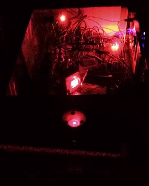
My first rudimentary ECDL optical cavity with grid 1800 lin. (illuminated picture)
"An optical cavity (also called an optical resonator) is a device capable of confining light at a certain frequency within it. The simplest optical resonator consists of two flat, parallel mirrors positioned so that photons are reflected many times before they can be lost by absorption or transmission. Optical resonators are used as spectrum analyzers or as optical filters because of their sensitivity to the frequency of light. Optical cavities are fundamental to the construction of lasers. Inside them, electromagnetic radiation is configured into standing waves that cancel at the interfaces. If the cavity's own frequency is adjusted to the energy of an optical transition of the substance contained within it (e.g., helium), the process of stimulated photoamplification can be achieved (see lasers and masers). The different possible configurations of standing waves are called cavity modes; longitudinal modes differ only in frequency, while transverse modes differ in frequency and intensity profile, along the beam section. Different types of resonators are distinguished by the position of the mirrors, their focal length and their number. These parameters must be chosen so that the cavity is stable (i.e., the beam size does not continuously grow as a result of multiple reflections). Some resonators can be configured to have no focal point or to have a beam with a very small waist. Typically, the optical cavities are designed to have a high Q-factor so that the beam is reflected many times with low attenuation. In this way, the linewidth of the beam is very narrow compared to that of the laser." (From Wikipedia).
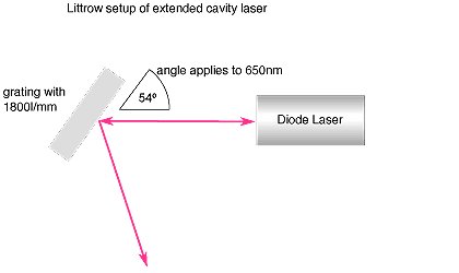
In my case having chosen to work with diodes, I have the need to have an efficient and low-cost optical cavity, which is why I chose this solution with a simple "Littrow" configuration.
The gratings are attractively priced, in short they are expensive!
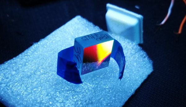
Here it is just opened, high cost expensive appearance, beautiful very beautiful, you can tell you are touching an important piece.
.jpg) |
We have to build the metal components step by step, and for this I have chosen quite a bit of solid aluminum, this time there will be no heat dissipation problems and the dissipation will be assured by the size and amount of aluminum present in an industrial base plate, bought second-hand and derived from industrial machines, so really an amount that can assure massive dissipation, also two peltier cells, put in such a way that they can really dissipate every bit of heat, first from the diode and then from the dissipation plate.
The temperature of the diode in this way is assured to the maximum.
The tests performed so far have definitely been above expectation which confirms to me that oversizing in the correct terms is an expense well made. |
The finished box has nothing to send to a factory-fresh, homemade but classy Zaphir! |
|
|
|
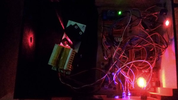
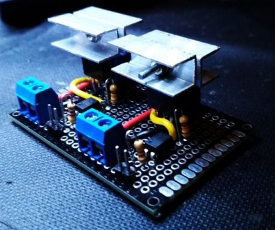
A key component of this laser is the opto-isolated relay I built, two 10 Ah channels, it handles the cooling of the peltier cells perfectly, frequency of operation is no longer an issue, a mechanical relay is not suitable.
It is another extremely expensive component, which I have reduced to a few euros of expense, except of course some HW and patience to build it.
As temperature sensors I use Texaxs Instruments components with a very small error level, reduced again by the redundancy of the sensors. The coupling makes for a remarkably effective system. (Yes there is no definitive circuit board yet, I reserve the right to make one later).
Note the dual power supply, the laser is completely separate from everything else, to avoid spikes and noise on the power signal the power part is not shared with the one powering the laser which has its own separate power supply.
18 volts for the laser (then adapted by its driver) and 5 volts for the Peltiers are correct power supply sizes for everything to work properly.
|
|
E finalmente LUCE FU'
.jpg)
|
This beautiful green rewards all labors, note the diode configuration!
.jpg)
|
Here is the final box, the display gives me an immediate check of the temperatures and operating parameters of the laser. The system is made to protect the diode from overtemperature or abnormal absorption, the protections turn off the laser before damage occurs.
.jpg)
|
Another interesting thing, with a few changes you can use a different color diode, just half an hour of work, and beware though that the laser incidence angle changes with wavelength (it has to be adjusted or goodbye emission quality) the incidence angle is not random and depends on the wavelength of the laser (mλ = a(sin ϕi + sin ϕd).) in short LEC = LDnD +LLnL +Lairnair. To put it simply mλ = 2a sin θ. |
|
Problem solved do you think? there is the optical cavity there is a fairly good quality emitted beam, I have achieved thermal stability at a fairly high level, yet it is still not all there.
To say that you have the thermal stability to avoid state jumps and keep the beam in TEM 0 for a long time without high-level tuning is perhaps optimistic, but today with 32 bits and higher resolution from Arduino programmable boards and clones, high quality sensor components, you are doing things that were previously unthinkable without high-level, and certainly much more expensive, electronics.
|
.jpg)
.jpg)
.jpg)
.jpg)
.jpg)
.jpg)